
Energy Efficiency and Thermal Simulations of a Retrofit LED Light Bulb by the University of Turku
Mika Maaspuro and Aulis Tuominen from the University of Turku investigated the energy efficiency of a LED driver mounted inside a retrofit light. The heat generation of the LEDs and the driver of the light bulb have been simulated and measured. A thermal model for the light bulb has been created and simulated using a Finite-Element-Method (FEM) software. Parameters of the model have been adjusted to match the temperature measurements which have been done with IR-camera and thermocouples.
Thermal management has a great influence on the reliability and on the life span of an LED light. The operational life of a LED light does not normally end suddenly but most likely the LED light encounters a steady reduction of light production at the end of its useful life span. Major decrease in light generation during theexpected normal lifetime of an LED is most likely caused by too high LED chip temperatures. This is a consequence of either failed thermal design or wrongly chosen ambient conditions of the light.
LEDs are not the only parts generating heat in LED lights. Some parts of the driver can reach high temperatures. Cooling them might not be as important as LEDs, but it makes sense to include these in the complete thermal model of an LED light.
There are numerous software tools for thermal and fluid dynamics simulations: ANSYS-CFX, Comsol Multiphysics, CoventorWare, FLUENT, STAR-CD, FEATFLOW (open-source) – just to name a few of them. Some of them solve complex fluid dynamics problems and some of them are FEM tools intended for solving various kinds of physical problems. In this study Comsol Multiphysics software and Heat Transfer Module were used. Comsol Multiphysics is a widely used FEM tool in universities and other educational institutes.
Thermal simulations can be an alternative to prototype building or to theoretical studies. Theoretical studies are normally limited to very simple structures and only for specific conditions. Theory of fluid dynamics is extremely complicated and design procedure to be used even for the simplest heatsinks become rather complicated. In general, the choices are either making simulations or building prototypes.
Simulations have some advantages when compared to prototyping.. Experimental methods can be too expensive or even impossible to make. Simulations can be used to discover the problematic parts in heat transfer from the LEDs or from the driver to ambient. Simulations make it possible optimize heat sink size, form and its material. Normally thermal interface materials are used to improve thermal conduction between adjacent components. Understanding of heat conduction, convection and radiation in the LED light can be expanded by simulations.
Thermal Model of the LED Lamp
The LED light bulb studied in this work is a commercial LED light rated at 9 W (110 VAC) or 10 W (220 VAC). The light bulb is rather large and heavy. Mass is 330 g, diameter 85 mm and length 160 mm. IP class is 30. Input voltage is specified for range 90 – 240 VAC. Color temperature 5700 K / 2850 K. Base type is E26/27. Light beam is 120°, and flux 570 lm. The number of LEDs is 14 and they do not have any lenses or diffusers directly above them. A shading dome covers all the LEDs.
 Figure 1: The CAD model of the retrofit LED light bulb
The 14 LED packages are on the thick (2 mm) aluminum MCPCB substrate plate. A thin insulator separates the conductive substrate and the copper layer. The aluminum substrate is mounted on the heatsink by using a thin layer of thermal grease between them. A polycarbonate dome covers the LED substrate plate. The driver is mounted inside the light base. Space around the driver is filled with thermal interface material. The same material is used to cover components mounted on top of the driver board.
 Figure 2: The CAD model of the surface mounted LED
 Figure 3: The CAD model of the driver
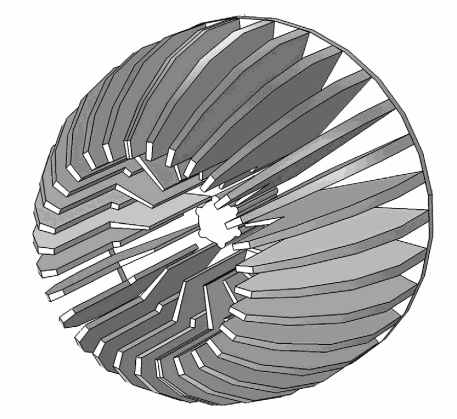
 Figure 4: The CAD model of the heatsink
The thermal resistance of the LED package can be found in a datasheet of the specific device. The FEM software uses a thermal conduction coefficient and this must be calculated from the thermal resistance. There is a following relationship between the thermal conduction and the thermal conduction coefficient.
Rth = ΔT : Pd = d: kA (1)
ΔT = temperature difference between LED chip and the surface closest the LED package [K]
d = distance between LED chip and the surface closest the LED package [m]
A = area through the heat is transferred [m2]
k = thermal conduction coefficient [W/(m·K)]
If k is calculated using only the area of the thermal pad, it becomes underestimated. Some amount of heat is also transferred through other surfaces. In order to find the correct value for k a thermal simulation was carried out for a case of single LED mounted on an efficient thermal sink. Value k was varied until the simulated temperature difference equalled the value calculated by using the thermal resistance. For the LED used in this light bulb Rth is 15ºC/W. In the simulations the thermal conduction coefficient k for the LED package becomes 4.45 W/(m·K).
The used surface mounted LED has a package size of approximately 2.5 x 2.5 x 1.3 mm. The component has six LEDs to be connected externally in parallel. Heat sources have been modeled as surface heats sources inside the package.
The main heat sources in the LED driver are the MOSFET, the freewheeling diode, the rectifier, the controller IC, the NTC resistor (used as a surge current limiter) and the inductor. Heat sources have been modeled either from surface sources inside a component package or volume sources.
The rather large and heavy heatsink has a form which is more spherical than conical. The size of every second fin has been reduced in order to give more airspace for heat flow from the center to out of the heatsink. In spite of this the center becomes the hottest point of the heatsink.
The CAD model differs from the real lamp in two details. In the real lamp, the heatsink fins are slightly curved to increase the surface area. In the model, the fins are straight ones. This limitation comes from the difficulty of generating such curved fins with the CAD tool. In the real lamp, the driver parts are surrounded with the thermal silicon. In the CAD model some parts of the driver are not entirely surrounded with the thermal silicon. This limitation comes from the difficulties of producing a mesh for such a structure. On the other hand, the CAD model is accurate enough in structural details.
Material Properties
A complete thermal model includes mechanical properties and material parameters. Material parameters need to be found in various sources. There can be some difference in parameters according to which reference is used. Especially properties of plastics can differ significantly depending on the exact concentrations of substances.
The dome of the light bulb is assumed to be polycarbonate plastics. The heatsink is cast aluminum alloy. One of the common materials used in heatsinks is alloy 6061 which is aluminum-magnesium-silicon alloy. The base of the light bulb is assumed to be ABS plastics, a common choice for LED light bulbs. The driver is mounted inside the base of the lamp. The remaining space is filled with thermally conductive gel. The gel should have suitable viscosity during LED lamp assembly. Afterwards it should feature high thermal conductivity, high volume resistivity, high dielectric strength, long term chemical stability and non-flammability. The typical thermal conductivity of silicone based gels is 0.8-2 W/(m·K) [10]. Thermally conducting grease is used between the LED substrate and the heatsink. The typical thermal conductivity of silicone based grease is 2-4 W/(m·K) [9].
Table 1 lists the main properties of the materials used in the LED light bulb. Density, thermal conductivity and specific heat are the most important ones. Emissivity factor will be defined entirely according to the surface finishing. Therefore it does not make sense to include emissivity factor in the table.
 Table 1: Material properties used for LED lamp simulations
 Figure 5: The 10 W LED driver and the load of 14 LEDs
Energy Efficiency of the Driver
The most inexpensive retrofit LED light bulbs usually have a non-isolated buck-based LED driver [7]. An isolated driver typically has a transformer which output voltage is normally much lower than the input line voltage. A non-isolated driver has the input galvanically connected to the output. High input line voltage is present at the output. The typical efficiency of a LED driver is between 80-90 %. The buck converter has the smallest amount of components of any type of drivers and therefore it may feature the highest efficiency. Most inexpensive driver designs do not include power factor correction circuitry. Therefore such a driver has a low power factor. In this case only 42% (Vin is 220 VAC, 50 Hz).
Component values are: C1, C2 are 100 nF, L1 is 3 mH, common mode choke L2 is 1 mH, C3 is 10 uF (electrolyte cap.), C4, C5 are 100 nF, R2 is 0.75 Ω. Power dissipation in each component was calculated with Spice simulations. The results are listed in table 2. These values are used for heat sources defined in the thermal model. The controller circuit used in the driver is one of the most common driver ic’s found in these kind of light bulbs. The MOSFET is rated for 0.9A drain current and for 600 V drain-source voltage. The Rds,on is relatively high (9.5 Ω) , but gate charge (5.9 nC) and Crss are relatively small ones.

Table 2: Power dissipation. Pin is 9.064 W, Pout is 7.987 W, Efficiency is 88.1%
Thermal Simulations
Comsol Multiphysics software has a “Joule Heating” model which covers the most common thermal problems where heat is generated by an electromagnetic source like current flowing through an ohmic device [3]. The main objectives of thermal simulations are solving internal and surface temperatures in stationary thermal conditions. The time needed for reaching stationary conditions in a lamp may even be several hours. Time dependent simulations which could show temperatures changing towards the stationary condition would be interesting but exhaustive because of needed memory size and computing time.
Heat conduction can be simulated by including “Heat Transfer in Solids” model into the simulations. This model will be chosen for all solid domains in the model.
Heat convection will be simulated by defining a “Convective Cooling” model for all outer surfaces. There are alternatives of how the convection factor will be defined. By choosing natural external convection, air is supposed to surround the lamp and air movement is caused only by the heating of the lamp itself. External forced cooling can be modeled either by entering a convection coefficient or using the forced external convection model. This makes it possible to simulate the effect external air flow could have. When defining convection, the position of the lamp must be decided. Most likely this lamp would be used as a ceiling lamp which is emitting light downwards. Natural convection should in that case make heat flow towards the base of the lamp. As it was more convenient to test the lamp in a laboratory by setting the dome to point upwards all simulations have been made for that case as well.
 Figure 6: Simulated stationary surface temperature of 10 W retrofit LED light bulb. External natural convection. Ambient temperature is 20ºC
Heat transfer in a gas filled domain is modeled by adding “Heat Transfer in Fluids” model into the simulation. This model is suitable for the gas (air) filled domain under the dome of the bulb. Gas pressure is expected to remain constant (isobaric process) although the heat generated by LEDs also heats the air and increases its volume. The sealing between the dome and the rest of the lamp is not gas-tight and extra air leaks out.
Radiation removes heat from the outer surfaces of the lamp. This can be modeled by including “Surface-to- Ambient Radiation” model into the simulation. The emissivity factor must be defined for all those materials which radiate heat from surface to ambient or from surface to other surfaces. Estimating roughly, about 20 % of the heat generated by the LEDs is radiated. The radiated heat can be modeled by selecting “Surface-to-Surface Radiation” in the “Joule Heating” model.
A domain with only a thin layer of some material causes difficulties in simulations. Mesh for such a domain has to be in dense comparison to other domains. This consumes memory and slows down the simulation. The thermal crease domain below the LED substrate plate and the insulator domain between the copper layer and the substrate plate are the thinnest domains in the model. Thickness of 0.2 mm is the practical minimum for the model. Including these domains increased simulation time from approximately half an hour to several hours (PC with 64-bit operating system, dual core CPU, 2.33 GHz, 8 GB memory). The software offers partial relief for thin conductive domains with “Highly Conductive Layer” or “Thin Thermally Resistive Layer” options. “Highly Conductive Layer” option was used for the copper foil (< 100 um) which otherwise would have been impossible to include in the model.
Internal temperatures can be studied by taking a cross sectional view of the light bulb. Figure 7 shows that the conical domain inside the light base which is the thermal silicon filling has a temperature of approximately 45ºC. Air just above the LEDs is also quite warm. The temperature of the MOSFET is distinctly more than 50 ºC.
") Figure 7: Simulated temperature of 10 W retrofit LED light bulb. (Cross section image. External natural convection. Ambient temperature is 20ºC)
Figure 7: Simulated temperature of 10 W retrofit LED light bulb. (Cross section image. External natural convection. Ambient temperature is 20ºC)
Studies [8] have indicated that convection coefficients of outer surfaces have significant effect on the junction temperature of a LED chip. It was also found that thermal conductivity of thermal grease has only a minor effect on the junction temperature. Another part of the study emphasizes the role thermal grease has in the cooling of a LED light [1].
 Figure 8: LED chip max. temperature vs. heat transfer coefficient of thermal convection
External natural convection equals the situation where convection heat transfer coefficient h is approximately 5 W/(m2·K). A higher value for h means forced external convection. A smaller value indicates natural convection is to some extent suppressed. Figure 8 shows the simulated maximum temperature of LED chip vs. the convection heat transfer coefficient. Emissivity factor of the heatsink is a parameter which is entirely defined by the surface finishing. If the emissivity factor is not known, it has to be estimated. Figure 9 offer the means for this and shows how the chip temperature increases when the emissivity reduces. These simulations were made for conditions where natural external convection prevails. Table 3. lists temperatures in external natural convection.
 Figure 9: LED chip max. temperature vs. emissivity of the heatsink
Thermal Validation
Thermal validation was done by using IR imaging and temperature measurements with type K thermocouples.
Recording measurements was delayed by two hours to make sure the lamp had reached its steady-state condition. An IR camera can give erroneous (too low) temperatures when pointed towards a surface of a low emissivity factor. Therefore it was found necessary to check the temperatures also with thermocouples. During the measurements, the lamp was mounted on a lamp holder which was fixed on a statue. The lamp holder was thermally isolated from the statue. Ambient air space around the lamp was large and its temperature remained constant (20ºC).
When measuring the LEDs, the dome had been removed. It was difficult to focus the IR camera carefully on the top of the LEDs as the camera had to be handled manually in front of the very bright LEDs.
 Figure 10: An IR image of the horizontally mounted LED light bulb: Heatsink 28-37ºC, Dome 25-27°C, Hot spots of the driver up to 50°C. Vin is 220 VAC
The largest differences in results between IR images and thermocouple measurements were found for LED top surface temperatures. Thermocouple measurement resulted in almost the same values as the simulations. These values can be considered as the most reliable results. This indicates the emissivity factor which was automatically set to 0.95 in the camera is too high. In order to match the IR image to thermocouple measurement the emissivity factor was reduced from 0.95 to 0.6. Figure 11 shows the corrected image of the LEDs.
 Figure 11: An IR image of the LEDs. Emissivity factor has been set to 0.6
 Table 3: Measured and simulated temperatures. Emissivity set to 0.95 in the IR camera . Vin is 220 VAC. Ambient temperature is 20ºC
Conclusions
The studied retrofit LED light bulb was found to be thermally well designed. The simulated temperatures of LED chips were found to be less than 85°C in case line input voltage is 220 VAC and external natural heat convection conditions prevail. The simulated and measured temperatures match relatively well. The main results are how the chip temperature varies according to the convection heat transfer factor or to the emissivity factor of the heatsink. The thermal model can further be improved by defining the material parameters, the heat convection factors, the emissivity factors more accurately. The accuracy of the mesh in FEM can also be improved with the expense of increased computing time. The lamp has a simple non-isolated driver which has good energy efficiency but a relatively low power factor. Electrical isolating between the LED wiring and the heatsink was a bit frail and this caused some doubts about electrical safety. This lamp is manufactured and bought in Asia and it may not have been intended for sale in Europe.
Acknowledgments:
This work is part of the project ReLED, which is supported by TEKES, the Finnish Funding Agency for Technology and Innovations.
References:
[1] Christian Alvin, et.al., “Thermal Analysis of Extruded Aluminum Fin Heat Sink for LED Cooling Application”, International Microsystems, Packaging, Assembly and Circuit Technology conference IMPACT, IEEE 2011.
[2] Kun Bai, et.al., ”Thermal simulation and optimization of high-power white LED lamps”, IEEE 2011.
[3] “Heat Transfer Module, User’s Guide for Comsol Multiphysics ver. 4.3”, Comsol Inc. 2011.
[4] J. Jakolenko, et.al., ”Thermal simulation and validation of 8W LED Lamp”, 12 th. Int. Conf. on Thermal, Mechanical and Multiphysics Simulation and Experiments in Microelectronics and Microsystems, EuroSimE 2011.
[5] Dmitri Kopeliovich, SubsTech, “http://www.substech.com”,.
[6] Xiaobing Luo, et.al., ”Thermal Design of a 16W LED Bulb Based on Thermal Analysis of a 4W LED Bulb”, Electronic Components and Technology Conference, IEEE 2010.
[7] Mika Maaspuro et.al.,“Energy Efficient Offline Buck-Based LED Driver”, LED Professional Magazine, Luger Research e.U. Institute for Innovation et Technology, March/April edition, 2012.
[8] Xiangjung Ma et.al., “Thermal analysis for high-power LED down-light”, IEEE 2011.
[9] “Thermal Management Silicones for Electronics”, Doc. SIL-820-EUR-0210 Momentive Performance Materials Inc., 2010.
[10] “Silicone Materials for LED Lighting Applications”, Doc. SIL-EM-LED-0310, Momentive Performance Materials Inc., 2010.